
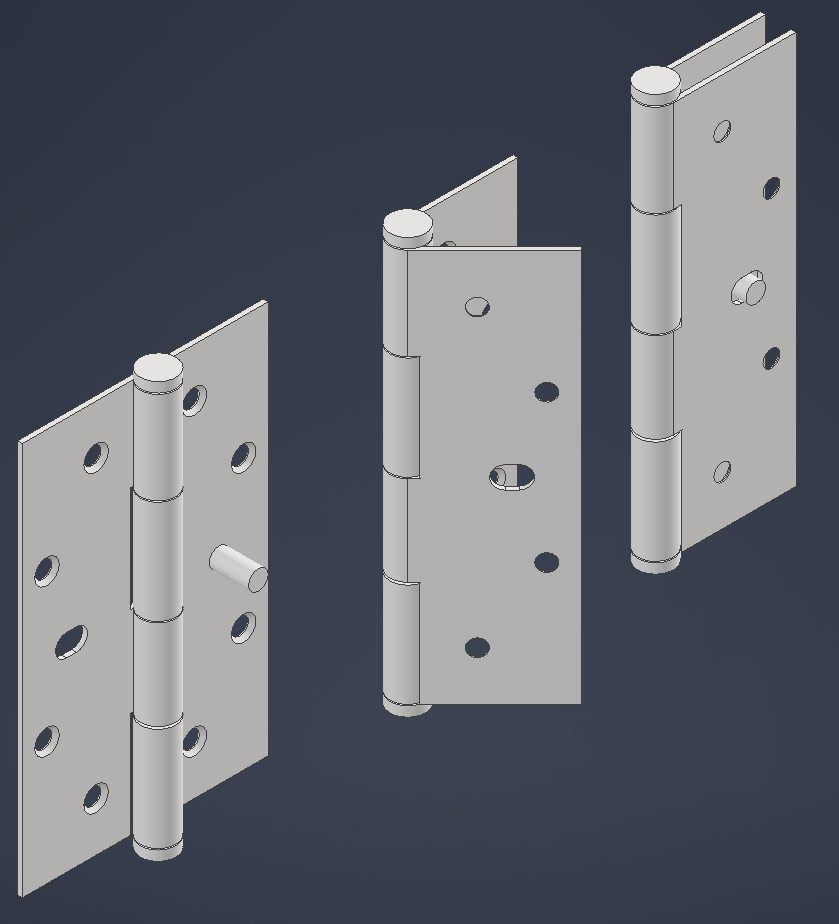
In design engineering, managing components or assemblies in multiple configurations is crucial for creating adaptable and efficient designs. Take, for example, a door hinge. It may need to be displayed in open and closed positions within different assemblies or in the same assembly at various times. Handling these variations effectively ensures streamlined workflows and consistency across projects.
Why Traditional Approaches Fall Short
Traditionally, designers would either create separate models for each configuration or rely on a single model updated manually for each state. These methods often lead to increased workload, errors, and file management complexities.
A Smarter Way to Manage Configurations
Autodesk Inventor offers a powerful solution to this challenge through the use of Model States. Model States allow you to create multiple representations of a part or assembly within a single file, each with its own unique parameters, features, and constraints. This not only simplifies file management, but also enhances productivity by enabling quick transitions between different configurations.
Understanding Model States
Inventor’s advanced design tools empower users to:
- Create variations of a part or assembly within one document.
- Independently control features, parameters, iProperties, and component suppression for each setup.
- Customise component representations for manufacturing, assembly instructions, or simulations.
Using Model States, you can efficiently manage different configurations without the need to maintain separate files for each variation.
To delve deeper into automation techniques, explore iLogic Automation for tips on enhancing productivity.
Setting Up Multiple Variations
The process of creating Model States is straightforward and applies similarly to both parts and assemblies. Here’s how you can set up multiple Model States:
- Create Your Base Part or Assembly
- Design your part or assembly, such as a hinge in its default position.
- Access the Model States Panel
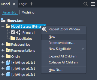
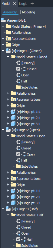
- In the Model Browser (the panel usually on the left side of the Inventor interface), locate the Model States node.
- Create a New Model State
- Right-click on the Model States node.
- Select New from the context menu.
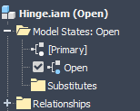
- A new Model State will appear within the list. Name the state descriptively, such as “Open” or “Closed.”
- Modify the New Model State
- Double-click on the new Model State to activate it.
- Adjust parameters, suppress features, or modify constraints. For instance, change the hinge’s angle to represent an open position.
- The changes you make are specific to this Model State and won’t affect others.
- Repeat for Additional States
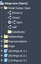
- Follow steps 3 and 4 to create states like “Half Open” or “Fully Extended.”
- Switching Between Model States
- Double-click any state to activate it and see the corresponding setup.
Using Model States in Assemblies
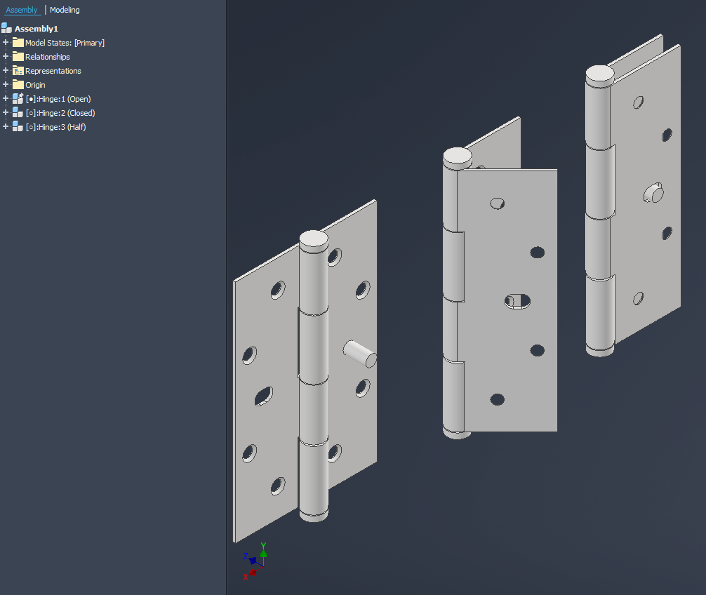
When you place a component with Model States into an assembly, you can assign different setups to various instances of the same part, within a single assembly.
Changing the Model State in an Assembly
How to Use Flexible Tools in Assemblies
- Insert the Component
- Insert the component into your assembly as usual.
- Select the Desired Model State
- In the assembly’s Model Browser, expand the component to view its options.
- Right-click the desired state and select Activate.
- Repeat for Other Instances
- If you have multiple instances of the component, you can set each one to a different Model State as needed.
Automating Configurations with iLogic
For increased efficiency, Autodesk Inventor’s iLogic feature allows you to automate activation of different setups. Here’s a basic example:
Component.ActiveModelState("Hinge:1") = "[Open]"Handling Component Name Changes
To prevent errors caused by changing component names, there are alternative methods to reference component occurrences:
- Use Occurrence Index
Reference components by their index in the assembly’s occurrences collection:
Dim oDoc As AssemblyDocument = ThisDoc.Document
Dim occr As ComponentOccurrence = oDoc.ComponentDefinition.Occurrences(1)
Component.ActiveModelState(occr.Name) = "[Open]" - Limitations: This approach is only reliable if the assembly structure remains static. Changes such as adding or removing occurrences before the referenced one can alter the index.
- Using Custom Attributes
Assign custom attributes for reliable reference them consistently, regardless of name or position. Here’s an example:
Dim oDoc As AssemblyDocument = ThisDoc.Document
Dim attrbSets As AttributeSetsEnumerator = oDoc.AttributeManager.FindAttributeSets("Demo")
Dim occr As ComponentOccurrence = Nothing

For Each attrbSet As AttributeSet In attrbSets
    If attrbSet.Name = "Demo" AndAlso attrbSet.Item(1).Name = "Demo1" Then
        occr = attrbSet.Item("Demo1").Parent.Parent.Parent
        Component.ActiveModelState(occr.Name) = "[Open]"
    End If
Next- Benefits: Attributes stay with the occurrence regardless of changes to names or assembly structure, making them a robust reference method.
To learn about attributes, refer to the Autodesk Inventor Help Documentation.
Enhancing Workflow Efficiency
Inventor’s configuration tools offer significant advantages:
- File Management: Minimise file clutter by storing multiple setups in a single file.
- Flexibility: Easily switch between configurations without altering original models.
- Automation: Use iLogic and custom attributes to streamline repetitive tasks.
For other ways to enhance efficiency and work with attributes, visit our guide on automating dimension placement.
Conclusion
Mastering configuration tools in Autodesk Inventor enables engineers to work smarter, not harder. Whether optimising hinge setups or managing complex assemblies, these features reduce errors and boost productivity. Combined with automation tools like iLogic, you can ensure consistency and precision in every project.
Streamline your design processes today and explore the full potential of Inventor’s advanced features!
Leave a Reply