
When adding annotations to drawings in Autodesk Inventor, it’s often useful to select specific points along the edges of objects, such as the start, midpoint, or endpoint of a line, similar to how you would when adding dimensions. Inventor’s API provides access to this selection system through the PointInferenceEnabled property.
By setting this property to true within an interaction event, users can see all inference points and access the inference data accordingly. So, all we need to do is filter out the parts we don’t want the user to see, right?
The Problem with Point Inference
The issue is that point inference overrides all selection filters and shows both the three main points (start, mid, and end) in green, as well as any other point on the drawing in yellow. It also highlights any object the mouse moves over. Worse still, these visual elements are tied to the event triggers, meaning you either get the ability to see and select everything or nothing. This approach can be confusing for end users, as they might assume they can select any highlighted point, even if it’s not intended.
Unless you’re happy with end users believing they can select anything and then filtering after they click, this method isn’t practical.
Can We Create Custom Selection Methods in Autodesk Inventor?
In short, yes. And here’s how.
Prerequisites
Please note that the following method works only in-process. This means it can be implemented in plugins, iLogic, and VBA, but applications external to Autodesk Inventor will fail with the event handlers used here.
Creating a Custom Selection Method
To recreate the desired functionality, we need to:
- Create a selection filtering system.
- Draw the endpoint graphics ourselves.
This involves using four event handlers:
- OnPreSelect: Filters and selects curve segments.
- OnStopPreSelect: Clears the selected curve when the user moves away.
- OnMouseMove: Finds the nearest point within a given threshold and adds a green circle to indicate selection.
- OnMouseClick: Collects the data when the user makes a selection.
Note: You can use Hot Reload to quickly make changes to the program without having to restart Inventor.
Selection Method Implementation
Below is the code implementation for the custom selection method:
private static Inventor.Application _invApp;
private static InteractionEvents oInteractEvents;
private static MouseEvents oMouseEvents;
private static SelectEvents oSelectEvents;
private static DrawingCurveSegment Curve;
private static PointIntentEnum Intent;
private static DrawingCurveSegment highlightedCurve;
private static Point2d previousPoint;
private static PointIntentEnum PointIntent;
private static InteractionGraphics IGraphics;
private static ClientGraphics CGrapics;
public void SelectGeometry()
{
// Create an InteractionEvents object.
oInteractEvents = _invApp.CommandManager.CreateInteractionEvents();
// Set references to mouse and select events.
oMouseEvents = oInteractEvents.MouseEvents;
oSelectEvents = oInteractEvents.SelectEvents;
// Ensure interaction is enabled.
oInteractEvents.InteractionDisabled = false;
oMouseEvents.MouseMoveEnabled = true;
IGraphics = oInteractEvents.InteractionGraphics;
CGrapics = IGraphics.OverlayClientGraphics;
// Set selection filter to DrawingCurveSegment.
oSelectEvents.AddSelectionFilter(SelectionFilterEnum.kDrawingCurveSegmentFilter);
// Attach event handlers.
oSelectEvents.OnPreSelect += OSelectEvents_OnPreSelect;
oSelectEvents.OnStopPreSelect += OSelectEvents_OnStopPreSelect;
oMouseEvents.OnMouseMove += OMouseEvents_OnMouseMove;
oMouseEvents.OnMouseClick += OMouseEvents_OnMouseClick;
// Start the InteractionEvents object.
oInteractEvents.Start();
}
private static void OSelectEvents_OnPreSelect(
ref object PreSelectEntity,
out bool DoHighlight,
ref ObjectCollection MorePreSelectEntities,
SelectionDeviceEnum SelectionDevice,
Point ModelPosition,
Point2d ViewPosition,
Inventor.View View)
{
if (PreSelectEntity is DrawingCurveSegment curve)
{
if (highlightedCurve != curve)
{
DeleteGreenCircle();
}
highlightedCurve = curve;
DoHighlight = true;
}
else
{
highlightedCurve = null;
DoHighlight = false;
}
}
private static void OSelectEvents_OnStopPreSelect(
Point ModelPosition,
Point2d ViewPosition,
View View)
{
highlightedCurve = null;
}
private static void OMouseEvents_OnMouseMove(
MouseButtonEnum Button,
ShiftStateEnum ShiftKeys,
Point ModelPosition,
Point2d ViewPosition,
Inventor.View View)
{
if (highlightedCurve != null && NearestPoint(ModelPosition) is Point2d p)
{
if (p != previousPoint)
{
DeleteGreenCircle();
}
ShowGreenCircle(p, View);
previousPoint = p;
}
else
{
DeleteGreenCircle();
}
}
private static void OMouseEvents_OnMouseClick(
MouseButtonEnum Button,
ShiftStateEnum ShiftKeys,
Point ModelPosition,
Point2d ViewPosition,
Inventor.View View)
{
try
{
if (Button == MouseButtonEnum.kLeftMouseButton && highlightedCurve != null)
{
Curve = highlightedCurve;
Intent = PointIntent;
// Stop the InteractionEvents object.
oInteractEvents.Stop();
// Detach event handlers.
oMouseEvents.OnMouseMove -= OMouseEvents_OnMouseMove;
oMouseEvents.OnMouseClick -= OMouseEvents_OnMouseClick;
oSelectEvents.OnPreSelect -= OSelectEvents_OnPreSelect;
oSelectEvents.OnStopPreSelect -= OSelectEvents_OnStopPreSelect;
// Clean up.
oMouseEvents = null;
oSelectEvents = null;
oInteractEvents = null;
// Proceed with your operations.
}
}
catch (Exception ex)
{
System.Diagnostics.Debug.Print(ex.ToString());
}
}
/// <summary>
/// Adds a green circle to the view at the specified point.
/// </summary>
/// <param name="point">The 2D point where the circle will be displayed.</param>
/// <param name="view">The Inventor view.</param>
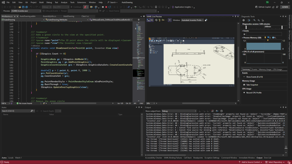
private static void ShowGreenCircle(Point2d point, Inventor.View view)
{
if (CGrapics.Count == 0)
{
GraphicsNode gn = CGrapics.AddNode(0);
PointGraphics pg = gn.AddPointGraphics();
GraphicsCoordinateSet gcs = IGraphics.GraphicsDataSets.CreateCoordinateSet(0);
double[] coordinates = { point.X, point.Y, 0 };
gcs.PutCoordinates(coordinates);
pg.CoordinateSet = gcs;
pg.PointRenderStyle = PointRenderStyleEnum.kEndPointStyle;
pg.BurnThrough = true;
IGraphics.UpdateOverlayGraphics(view);
}
}
/// <summary>
/// Removes the green circle from the view.
/// </summary>
private static void DeleteGreenCircle()
{
if (CGrapics != null && CGrapics.Count != 0)
{
CGrapics.ItemById[0].Delete();
PointIntent = 0;
}
}
/// <summary>
/// Finds the nearest point (start, mid, or end) on the highlighted curve within a threshold distance.
/// </summary>
/// <param name="modelPosition">The current mouse position in model coordinates.</param>
/// <returns>The nearest Point2d if within threshold; otherwise, null.</returns>
private static Point2d NearestPoint(Point modelPosition)
{
PointIntent = 0;
if (highlightedCurve == null || modelPosition == null) { return null; }
Point2d startPoint = highlightedCurve.StartPoint;
Point2d endPoint = highlightedCurve.EndPoint;
Point2d midPoint = _invApp.TransientGeometry.CreatePoint2d(
(startPoint.X + endPoint.X) / 2.0,
(startPoint.Y + endPoint.Y) / 2.0);
Point2d currentPoint = _invApp.TransientGeometry.CreatePoint2d(modelPosition.X, modelPosition.Y);
// Define the threshold distance.
double threshold = 0.1;
// Create a list to store points within the threshold.
var nearbyPoints = new List<(Point2d Point, double Distance)>();
double d;
if ((d = sPoint.DistanceTo(tPoint)) <= threshold) { nearbyPoints.Add((sPoint, d)); } // Start Point
if ((d = mPoint.DistanceTo(tPoint)) <= threshold) { nearbyPoints.Add((mPoint, d)); } // Mid Point
if ((d = ePoint.DistanceTo(tPoint)) <= threshold) { nearbyPoints.Add((ePoint, d)); } // End Point
if (nearbyPoints.Count == 0) { return null; }
// Find the closest point among the nearby points.
var closestPoint = nearbyPoints.OrderBy(p => p.Distance).First().Point;
// Set the PointIntent based on the closest point.
PointIntent = (nPoint == sPoint) ? PointIntentEnum.kStartPointIntent : (nPoint == mPoint ? PointIntentEnum.kMidPointIntent : PointIntentEnum.kEndPointIntent);
return closestPoint;
}To use this method, simply call the SelectGeometry() function within your Inventor add-in or script.
Understanding How Selection Code Works
This code sets up an interaction event within Autodesk Inventor to allow users to select only the start, mid, or end points of a drawing curve segment. It uses custom event handlers to control the selection process and provide visual feedback.
Key Components
- Global Variables: Manage the Inventor application object, interaction events, mouse and selection events, and graphical elements.
- Event Handlers: Manage the filtering, highlighting, and selection of curve segments.
- Helper Functions: Show and delete green circles for visual feedback and determine the nearest point to the mouse position.
For a deeper dive into how Inventor manages user interactions, check out the official User Interaction documentation.
How Auto Dimension Placement Led to Custom Selection Methods
Interestingly, this journey into creating custom selection methods was sparked by the need for a tool to help with auto-dimension placement in Inventor. If you’re curious, explore more about how automating dimension placement in drawings can streamline your design process. Learn more about automating dimension placement.
Final Thoughts
Customising selection methods in Autodesk Inventor unlocks new possibilities for tailoring the tool to specific project needs. By leveraging interaction events and custom graphics, you can provide users with a more intuitive experience while maintaining precise control over their selections. Whether you’re working with plugins, iLogic, or VBA, these approaches ensure that your workflow remains streamlined and efficient.
If you’re exploring further ways to enhance your design processes, consider checking out creating geometry or placing objects in Inventor. The potential is only limited by your imagination and willingness to experiment.
Leave a Reply