
Automating the placement of objects in Autodesk Inventor assemblies can significantly enhance efficiency in design workflows. This guide delves into using the Inventor API to position and orient parts within an assembly, focusing on the manipulation of matrices for precise control.
Establishing a Connection to Inventor
Begin by obtaining a reference to the active Inventor application and the active document, which should be an assembly document in this context:
Inventor.Application _invApp = GetInventor();

AssemblyDocument oDoc = (AssemblyDocument)_invApp.ActiveDocument;

TransientGeometry oTG = _invApp.TransientGeometry;
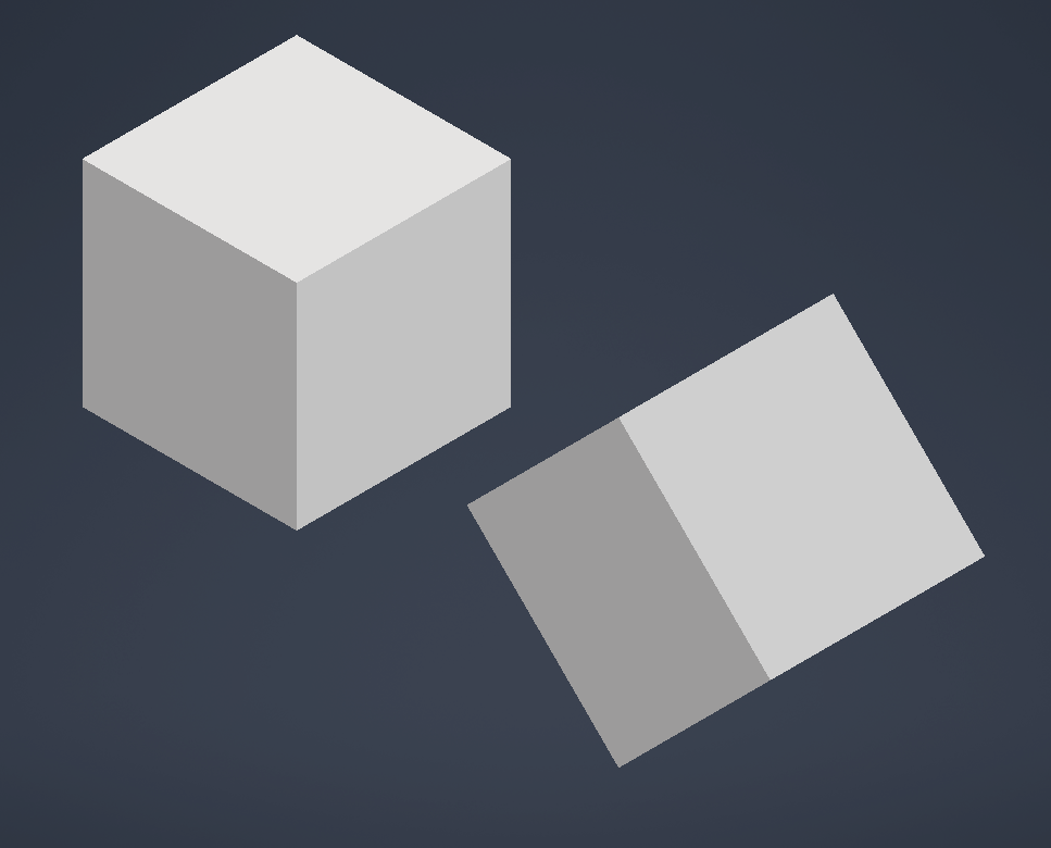
String filePath = "C:\\temp\\10x10x10 cube.ipt";Dim _invApp As Inventor.Application = GetInventor()
Dim oDoc As AssemblyDocument = _invApp.ActiveDocument
Dim oTG As TransientGeometry = _invApp.TransientGeometry
Dim filePath As String = "C:\temp\10x10x10 cube.ipt"To see how to get Inventor check out this page.
Understanding Positional Matrices in Autodesk Inventor
What is a Positional Matrix?
A positional matrix, in the context of 3D modeling and CAD software like Autodesk Inventor, is a mathematical construct used to define an object’s position, rotation, and scale in three-dimensional space. It is a fundamental concept in computer graphics and geometry, enabling precise control over the transformation of objects within a digital environment.
How Does a Positional Matrix Work?
A 3D matrix is typically represented as a 4×4 grid:
1 0 0 0
0 1 0 0
0 0 1 0
0 0 0 1
Rows and Columns: Each row and column of the matrix corresponds to a dimension in 3D space (X, Y, Z) and an additional dimension for homogeneous coordinates, which are used for mathematical convenience and to represent translations.
Identity Matrix: The matrix shown above is known as an identity matrix. It represents no change; that is, any object transformed by this matrix will not be rotated, moved, or scaled. It’s effectively the default or “blank” state of an object in 3D space.
Transformation: To change an object’s position, rotation, or scale, the values within the matrix are modified. Each element of the matrix has a specific role in how it affects the transformation of an object:
- Position: The last column of the matrix (except the bottom row) is used to specify the object’s position in 3D space.
- Rotation: The first three columns and rows can be used to define the object’s orientation or rotation. They represent the object’s local axes after rotation.
- Scale: The diagonal elements (top left to bottom right) can represent the scale of the object, although uniform scaling requires a more complex approach to maintain consistent rotation.
Basic Placement
In practice, rather than manually creating and altering matrix values, Inventor provides methods to create and modify these transformations.
The code below shows how to create a blank positional matrix that defines the part’s rotation and position. This matrix is then used to add an occurrence of the part to the assembly:
Matrix matrix = oTG.CreateMatrix();

oDoc.ComponentDefinition.Occurrences.Add(filePath, matrix);Dim matrix As Matrix = oTG.CreateMatrix()
oDoc.ComponentDefinition.Occurrences.Add(filePath, matrix)This matrix, by default, places the object at the assembly’s origin without any rotation.
Why Use a Positional Matrix?
Unified Transformations: A single matrix can represent multiple transformations — translation, rotation, and scaling — in a compact and efficient manner. This simplifies the manipulation of objects in 3D space.
Precision and Control: Matrices allow for precise control over object transformations, essential for engineering and design tasks in Inventor.
Ease of Use: While the underlying mathematics can be complex, Inventor abstracts much of this complexity, offering tools and functions that manipulate matrices without requiring direct interaction with the matrix elements. This makes it user-friendly to perform sophisticated transformations.
Modifying Position

To change an object’s position, apply a translation to the matrix:
Matrix matrix = oTG.CreateMatrix();

oDoc.ComponentDefinition.Occurrences.Add(filePath, matrix);

matrix.SetTranslation(oTG.CreateVector(2, 0, 0));

oDoc.ComponentDefinition.Occurrences.Add(filePath, matrix);Dim matrix As Matrix = oTG.CreateMatrix()
oDoc.ComponentDefinition.Occurrences.Add(filePath, matrix)
matrix.SetTranslation(oTG.CreateVector(2, 0, 0))
oDoc.ComponentDefinition.Occurrences.Add(filePath, matrix)This moves the second occurrence of the part 2 cm along the X-axis. The position can be adjusted in all three dimensions (X, Y, Z) by altering the values passed to CreateVector.
Note that the matrix will always be in cm no matter what the units on the document.
Modifying Rotation
There are two main ways to set the rotation of the matrix with Inventor API, set the rotation around an axis or align a vector with another vector.
To use the first method SetToRotation requires the rotation angle, axis, and pivot point:
Matrix matrix = oTG.CreateMatrix();

oDoc.ComponentDefinition.Occurrences.Add(filePath, matrix);

matrix.SetToRotation(45 * (Math.PI / 180), oTG.CreateVector(0,0,1), oTG.CreatePoint(0,0,0));
matrix.SetTranslation(oTG.CreateVector(2, 0, 0));

oDoc.ComponentDefinition.Occurrences.Add(filePath, matrix);Dim matrix As Matrix = oTG.CreateMatrix()
oDoc.ComponentDefinition.Occurrences.Add(filePath, matrix)
matrix.SetToRotation(45 * (Math.PI / 180), oTG.CreateVector(0, 0, 1), oTG.CreatePoint(0, 0, 0))
matrix.SetTranslation(oTG.CreateVector(2, 0, 0))
oDoc.ComponentDefinition.Occurrences.Add(filePath, matrix)This rotates the part 45 degrees around the Z-axis. Converting degrees to radians is necessary as the rotation angle is expected in radians.
To convert use: deg × (Pi ÷ 180)
CreateVector allows us to create the axis to rotate around, in this case it is aligned with the Z axis. The last requirement is the point of rotation, in this case set to 0 in all axis so that we only get the rotation without a position change.
The second method SetToRotateTo requires just two vectors:
Matrix matrix = oTG.CreateMatrix();

oDoc.ComponentDefinition.Occurrences.Add(filePath, matrix);

matrix.SetToRotateTo(oTG.CreateVector(1, 0, 0), oTG.CreateVector(0.5, 0.5, 0));
matrix.SetTranslation(oTG.CreateVector(2, 0, 0));

oDoc.ComponentDefinition.Occurrences.Add(filePath, matrix);Dim matrix As Matrix = oTG.CreateMatrix()
oDoc.ComponentDefinition.Occurrences.Add(filePath, matrix)
matrix.SetToRotateTo(oTG.CreateVector(1, 0, 0), oTG.CreateVector(0.5, 0.5, 0));
matrix.SetTranslation(oTG.CreateVector(2, 0, 0))
oDoc.ComponentDefinition.Occurrences.Add(filePath, matrix)This aligns the part’s X-axis with a vector halfway between the X and Y axes, providing a nuanced control over the part’s orientation.
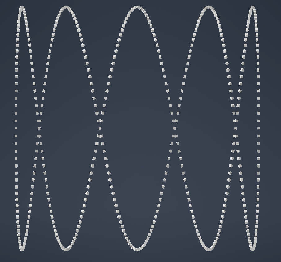
Example: Placing Parts Along a Circular Path
Illustrating a practical application, the following code places parts along a sine wave path that wraps around the Y-axis, rotating each part to align with the curve’s direction:
Matrix matrix = oTG.CreateMatrix();

double radius = 50; // Radius of the circular path
double amplitude = 50; // Height of the wave
double frequency = 0.2; // Frequency of the wave
int numPoints = 500; // Number of occurrences

for (double i = 0; i < numPoints; i++)
{
    // angle of circular path
    double angle = 2 * Math.PI * i / 100;

    // Circular path in XZ-plane
    double x = radius * Math.Cos(angle);
    double z = radius * Math.Sin(angle);

    // Sine wave modulation along Y-axis
    double y = amplitude * Math.Sin(frequency * angle);

    // Tangent vector components
    double dx = -radius * Math.Sin(angle);
    double dy = amplitude * frequency * Math.Cos(frequency * angle);
    double dz = radius * Math.Cos(angle);

    matrix.SetToRotateTo(oTG.CreateVector(1, 0, 0), oTG.CreateVector(dx, dy, dz));
    matrix.SetTranslation(oTG.CreateVector(x, y, z));

    oDoc.ComponentDefinition.Occurrences.Add(filePath, matrix);
}Dim matrix As Matrix = oTG.CreateMatrix()
Dim radius As Double = 50 ' Radius of the circular path
Dim amplitude As Double = 50 ' Height of the wave
Dim frequency As Double = 0.2 ' Frequency of the wave
Dim numPoints As Integer = 500 ' Number of occurrences
For i As Double = 0 To numPoints - 1
' angle of circular path
Dim angle As Double = 2 * Math.PI * i / 100
' Circular path in XZ-plane
Dim x As Double = radius * Math.Cos(angle)
Dim z As Double = radius * Math.Sin(angle)
' Sine wave modulation along Y-axis
Dim y As Double = amplitude * Math.Sin(frequency * angle)
' Tangent vector components
Dim dx As Double = -radius * Math.Sin(angle)
Dim dy As Double = amplitude * frequency * Math.Cos(frequency * angle)
Dim dz As Double = radius * Math.Cos(angle)
matrix.SetToRotateTo(oTG.CreateVector(1, 0, 0), oTG.CreateVector(dx, dy, dz))
matrix.SetTranslation(oTG.CreateVector(x, y, z))
oDoc.ComponentDefinition.Occurrences.Add(filePath, matrix)
NextThis script not only demonstrates positioning but also dynamically adjusts each part’s orientation to maintain alignment with the curve, showcasing the power and flexibility of using matrices for object placement in Inventor.
Leave a Reply