Revolutionizing Autodesk Inventor with a bespoke user interface, our solution accelerates the design process. Delve into our journey of crafting a custom interface tailored for speed, transforming heat exchanger circuit design.
What is a custom user interface?
A custom user interface is a tailored method enabling users to interact with a system in a manner aligned with specific requirements. Typically presented as a graphical user interface (GUI), it optimizes data entry speed and enhances control over input methods, thereby bolstering system reliability and efficiency.
Beyond enhancing data entry speed and control, custom user interfaces offer adaptable design elements that cater precisely to user needs. They allow for personalized layouts, specialized functionalities, and intuitive workflows tailored to specific tasks or user groups. This level of customization not only boosts efficiency but also streamlines user experience, minimizing errors and ensuring smoother interaction with the system.
Creating a custom user interface for Inventor
The Problem
A client had been relying on a macro within a outdated software program to assist in the design of cooling circuits for heat exchangers, but they sought a replacement for this aging tool. Initially, the solution involved developing a plugin for Inventor that mirrored the existing features. However, testing exposed a common issue shared by both the old and new solutions: they were sluggish to the point where designs were first sketched out on paper and then transferred to the computer.
Recognizing the need for a more efficient interface, one unhindered by the program’s processing speed, became evident. Such an interface would enable rapid design creation and also introduce the capability to implement error detection, an enhancement that was previously unattainable.
The Solution
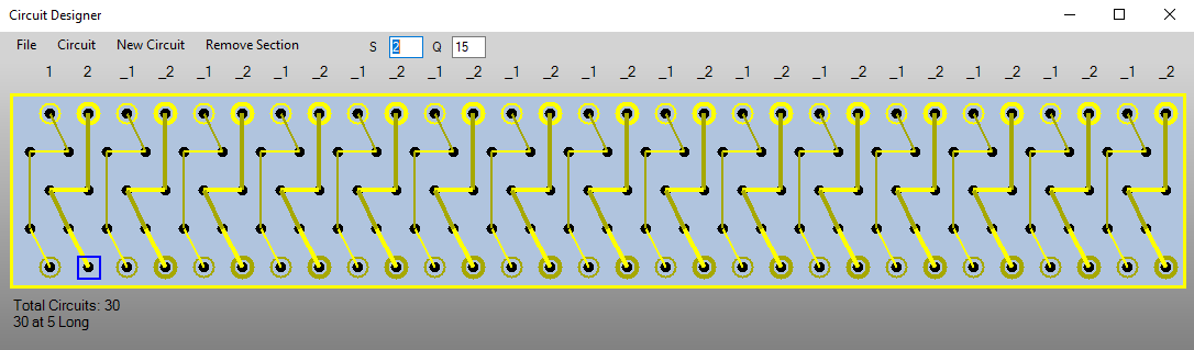
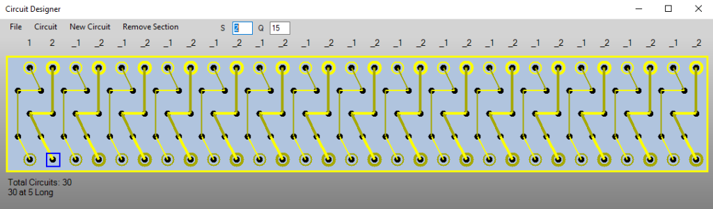
A dynamic user form capable of adapting to any heat exchanger configuration was crafted with a clever use of a picture box. Each time a user made a change, the system promptly redrew the image, taking just a fraction of a second. This approach allowed the form to seamlessly adjust to a myriad of possible configurations, offering an instant, responsive appearance to new modifications.
However, employing a picture box introduced its own set of challenges. Data had to be maintained separately, causing the image to represent data rather than the layout itself. This transformation made it possible to execute actions like copying sections or checking for overlapping parts but also introduced additional complexity. Now, there were two distinct systems to manage, increasing the potential for errors.
Creating the image itself proved relatively straightforward, as it utilized a side view of the heat exchanger. Basic shapes like circles and lines are employed to represent the various parts. User interaction with the image was achieved by referencing the mouse’s position and cross-referencing it with a list of nodes to determine the nearest node. This process facilitates implementing any required changes within the image.
Once the design was finalized, it needed to be translated into Inventor. Based on the data within the designer, assemblies and drawings could be generated. Much of the required code was adapted from previous prototypes. The significant change now was that the process no longer required user visibility. Consequently, the creation could take place in the background of Inventor. Thus significantly expediting the overall process by relieving Inventor from processing the graphics.
In Conclusion
The custom interface significantly accelerates the design and validation of circuits, streamlining the entire process. With designs now seamlessly integrated into Inventor, they can be effortlessly examined alongside the main assembly without the hassle of exporting and overlaying various drawings across multiple programs. This shift also alleviated the company’s dependence on the old software, effectively reducing licensing costs.
Moreover, the program opened up the door for anyone to create circuits. No longer is their a need for a licensed program to undertake the design work. A representation of the layout could be conveniently transferred from one program to another via a concise string of characters, making it easily shareable through email or collaboration platforms like Microsoft Teams.