Crafting a single use program for a large AutoCAD project. saving weeks of meticulous layout work through the use of a simple program to automate AutoCAD. Dive into how this bespoke solution streamlined equipment placement in complex, non-linear tunnels, revolutionizing efficiency within a singular project.
A single use AutoCAD program
The Project
A client faced the formidable challenge of laying out a detailed side view of their equipment within two tunnels, each spanning nearly a kilometre in length. Complicating matters was the fact that the tunnels were not flat, yet the rollers needed to be precisely positioned horizontally. Furthermore, the rollers had to overlap by half a meter and fit within a 400mm-tall enclosure.
To tackle this complex project, the tunnels were divided into various sections, each with its own gradient and estimated roller lengths. This approach allowed for the efficient batch production of rollers with consistent lengths, rather than having to manufacture rollers of varying sizes. The task involved accurately placing rollers of the appropriate length, determining positions that accommodated all the rollers while also integrating mounting bracketry. The estimated effort for this meticulous task was approximately three months worth of work.
The Solution
The initial challenge was to create a block for each part to be inserted in the drawing, complicated by the varying lengths of the rollers. AutoCAD’s parametric block feature came to the rescue, allowing the length to be adjusted by modifying a single parameter. Then integrating a code section to alter this parameter along with another to place the block, which had previously been written for a different project. This combination enabled the placement of all parts in AutoCAD.
Obtaining positional data from Excel was a relatively straightforward process; simply linking to the active document and extracting the necessary cell information from the designated columns, while looping through each row.
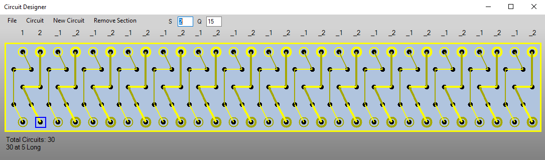
The most intricate part of the task was determining the placement positions for each block. Calculating the X-coordinate for the rollers was relatively simple, involving multiplying the roller number by the length of the rollers in each section minus the offset. However, the Y-coordinate was more complex, as the rollers needed to overlap and to fit within the angled enclosure. To address this, the program compiled a list of potential positions for each roller at 1mm intervals. It then further refined this list by eliminating positions where another roller couldn’t fit at both ends. Once complete for every roller it initiated a recursive section of code, starting with the first roller and placing it in its initial feasible position. This code section systematically assessed whether the next roller would fit, moving to the next roller if it did, or retracing a step if it didn’t. This iterative process continued until a viable solution was found or an error occurred. Once the position was determined, it was a matter of placing the blocks and using trigonometry to calculate the precise positions required for the bracketry.
In Conclusion
The programming and testing phase demanded approximately two and a half days, with each program execution taking around two minutes per tunnel. The program’s efficient capability to navigate through each section of the tunnels unearthed some issues with the initial roller length calculations. In certain sections, discrepancies in the offset calculations posed challenges, as the program had adopted some shortcuts to determine positions. To account for this, larger offsets than theoretically required were employed to prevent rollers from colliding with the enclosure. Another section encountered a different complication. Due to the slope’s angle, the preceding three sections rendered the fourth section impractical. The remedy involved halving the roller length in one particular section.
Fortunately, this adjustment was implemented early in the project, without any complications. Had the project adhered to the original timeline, where each section was immediately sent to manufacturing upon completion, revisiting a section for modification would have introduced major logistical challenges.
However, the journey wasn’t without its share of challenges. The program was written for AutoCAD’s COM interface, which, as it turned out, appeared to be one of the less supported methods for accessing AutoCAD. Not only did documentation on the objects within the API prove elusive, but a substantial bug within the interface itself was also discovered. Ideally, when a command is issued through an interface, the process should patiently wait for a response before proceeding with the next command, as only one command can be processed at a time. Unfortunately, this expected behaviour wasn’t consistently observed. The ideal resolution would have been to create a custom exception handler to manage this issue. However, considering that reliability was not an immediate concern and time was of the essence, the pragmatic approach was to introduce a fraction of a second delay between commands, ensuring that the program progressed as intended. This solution did not always prevent the error but improved the reliability enough for a single use program.