
Introduction
Parametric blocks in AutoCAD are powerful tools that enable users to insert blocks with varying dimensions and properties, maintaining consistency and efficiency in design. This guide will walk you through creating a parametric block, placing it via the API, and how this can be leveraged to automate the drawing process.
Creating a Parametric Block in AutoCAD
Step 1: Define Your Block Geometry
- Start by creating the geometry of your block in AutoCAD. This could be any shape or combination of shapes that fit your design requirements.
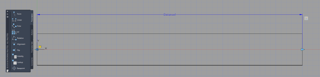
Step 2: Add Parameters and Actions
- Introduce parameters (like distance, angle, etc.) that define the constraints of your block.
- Attach actions to these parameters (like stretch, rotate, etc.) that determine how the block geometry responds to changes in parameter values.
Step 3: Test the Block
- Before finalizing, test the parametric block by modifying the parameters and ensuring the geometry updates as expected.
Step 4: Save the Block
- Once satisfied with the functionality, save your block for future use.
Placing the Block via the API
Using the AutoCAD API to Automate Block Placement
The following code snippet demonstrates how to place a parametric block in an AutoCAD document using the API:
// Get the active document
AcadDocument oDoc = _Auto.ActiveDocument;

// Placement position X, Y, Z
double[] position = new double[] { 100, 100, 0 };

// Place block
AcadBlockReference acadBlock = oDoc.Layouts.Item(2).Block.InsertBlock(position, "Tube ∅60", 1, 1, 1, 0);

// Edit parameter that matches the parameterName
string parameterName = "Distance1";
object[] acadDynamics = acadBlock.GetDynamicBlockProperties();
foreach (AcadDynamicBlockReferenceProperty BlockRef in acadDynamics.Cast<AcadDynamicBlockReferenceProperty>())
    if (parameterName == BlockRef.PropertyName) { BlockRef.Value = (double)10; }

// Update the block with the changes
acadBlock.Update();' Get the active document
Dim oDoc As AcadDocument = _Auto.ActiveDocument
' Placement position X, Y, Z
Dim position As Double() = New Double() {100, 100, 0}
' Place block
Dim acadBlock As AcadBlockReference = oDoc.Layouts.Item(2).Block.InsertBlock(position, "Tube ∅60", 1, 1, 1, 0)
' Edit parameter that matches the parameterName
Dim parameterName As String = "Distance1"
Dim acadDynamics As Object() = acadBlock.GetDynamicBlockProperties()
For Each BlockRef As AcadDynamicBlockReferenceProperty In acadDynamics.Cast(Of AcadDynamicBlockReferenceProperty)()
If parameterName = BlockRef.PropertyName Then
BlockRef.Value = CDbl(10)
End If
Next
' Update the block with the changes
acadBlock.Update()Explanation of the Code:
- The code requires the
_Autobe a reference to the AutoCAD application, see this page for how to set this up. - The code begins by accessing the active AutoCAD document.
- It specifies the position for the block placement. If your only working in 2D then you can leave the Z position as zero.
- The
InsertBlockmethod places the block in the specified layout. Make sure that the name exactly matches that of the block. - The block’s dynamic properties are then accessed and edited. It may be worth using a dictionary if you whish to edit multiple parameters per block.
- Finally, the block is updated to reflect the changes.

Simply running the code within a loop can show the speed at which AutoCAD can place and edit 100 blocks.
Applications in Automating the Drawing Process
Streamlining Repetitive Tasks
- Batch Operations: Automating the placement of parametric blocks is particularly useful for batch operations where the same block is used multiple times across different drawings with varying parameters.
- Minimizing Manual Errors: Automation reduces the risk of human error in repetitive tasks, leading to higher accuracy and quality in drawings.
Integrating with Data Sources
- Data-Driven Design: Automate block placement and parameterization by integrating with external data sources, such as Excel or databases, allowing for data-driven design modifications.
- Real-Time Updates: Implement real-time updates in drawings based on changes in data sources, enhancing responsiveness to project changes.
Innovative Design Solutions
- Exploring Design Variations: Quickly generate multiple design variations by changing parameters programmatically, encouraging exploration and innovation.
- Complex Geometries: Simplify the creation and manipulation of complex geometries that would be time-consuming to handle manually.
Leave a Reply